

What Is Center Of Rotation

Sketch 1: Instantaneous center P of a moving plane
The instant center of rotation (also, instantaneous velocity center,[1] instantaneous center, or instant eye) is the indicate fixed to a trunk undergoing planar movement that has zilch velocity at a particular instant of fourth dimension. At this instant, the velocity vectors of the other points in the torso generate a circular field around this point which is identical to what is generated by a pure rotation.
Planar movement of a trunk is oft described using a plane effigy moving in a 2-dimensional airplane. The instant middle is the bespeak in the moving airplane effectually which all other points are rotating at a specific instant of time.
The continuous movement of a aeroplane has an instant center for every value of the time parameter. This generates a curve called the moving centrode. The points in the fixed plane respective to these instant centers grade the stock-still centrode.
The generalization of this concept to 3-dimensional space is that of a twist effectually a screw. The spiral has an axis which is a line in 3D infinite (non necessarily through the origin), and the screw likewise has a finite pitch (a fixed translation along its axis corresponding to a rotation about the spiral axis).
Pole of a planar displacement [edit]
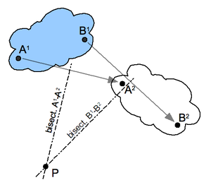
Sketch 2: Pole of a planar displacement
The instant center tin can be considered the limiting case of the pole of a planar deportation.
The planar deportation of a body from position 1 to position 2 is defined past the combination of a planar rotation and planar translation. For any planar displacement there is a betoken in the moving body that is in the same place before and after the displacement. This indicate is the pole of the planar displacement, and the deportation can be viewed as a rotation effectually this pole.
Structure for the pole of a planar deportation: Start, select two points A and B in the moving body and locate the corresponding points in the two positions; see the illustration. Construct the perpendicular bisectors to the 2 segments AiAtwo and B1B2. The intersection P of these two bisectors is the pole of the planar displacement. Detect that A1 and Aii lie on a circle around P. This is truthful for the corresponding positions of every point in the body.
If the 2 positions of a body are separated past an instant of time in a planar move, then the pole of a deportation becomes the instant center. In this case, the segments constructed between the instantaneous positions of the points A and B become the velocity vectors VA and VB. The lines perpendicular to these velocity vectors intersect in the instant centre.
The algebraic structure of the Cartesian coordinates can be arranged every bit follows: The midpoint betwixt and has the Cartesian coordinates


and the midpoint between and has the Cartesian coordinates


The ii angles from to and from to measured counter-clockwise relative to the horizontal are determined by

taking the correct branches of the tangent. Let the eye of the rotation take distances and to the 2 midpoints. Assuming clockwise rotation (otherwise switch the sign of ):


Rewrite this as a 4 × four inhomogeneous organisation of linear equations with 4 unknowns (the two distances and the two coordinates of the centre):


The coordinates of the eye of the rotation are the first ii components of the solution vector

Pure translation [edit]
If the deportation between ii positions is a pure translation, then the perpendicular bisectors of the segments A1Bi and A2Bii class parallel lines. These lines are considered to intersect at a betoken on the line at infinity, thus the pole of this planar displacement is said to "prevarication at infinity" in the direction of the perpendicular bisectors.
In the limit, pure translation becomes planar movement with point velocity vectors that are parallel. In this instance, the instant centre is said to lie at infinity in the direction perpendicular to the velocity vectors.
Instant center of a wheel rolling without slipping [edit]


Instant eye of rotation of a rolling wheel broken down into points. By breaking downward the rolling cycle into several points, it tin be more hands seen how all points of the bike rotate effectually a single point at each instant. This point is the instant center of rotation, shown in black.
Consider the planar motility of a circular bicycle rolling without slipping on a linear route; see sketch 3. The wheel rotates around its axis M, which translates in a management parallel to the route. The betoken of contact P of the wheel with road does not slip, which means the point P has nix velocity with respect to the route. Thus, at the instant the bespeak P on the bicycle comes in contact with the road it becomes an instant middle.
The set up of points of the moving bicycle that become instant centers is the circle itself, which defines the moving centrode. The points in the fixed plane that correspond to these instant centers is the line of the road, which defines the stock-still centrode.
The velocity vector of a point A in the wheel is perpendicular to the segment AP and is proportional to the length of this segment. In particular, the velocities of points in the bike are determined by the angular velocity of the wheel in rotation effectually P. The velocity vectors of a number of points are illustrated in sketch 3.
The farther a point in the bike is from the instant center P, the proportionally larger its speed. Therefore, the point at the top of the wheel moves in the same management as the centre G of the wheel, just twice every bit fast, since it is twice the altitude away from P. All points that are a distance equal to the radius of the cycle 'r' from point P move at the same speed as the bespeak Thou but in unlike directions. This is shown for a point on the wheel that has the same speed as M simply moves in the direction tangent to the circle around P.
Relative heart of rotation for two contacting planar bodies [edit]
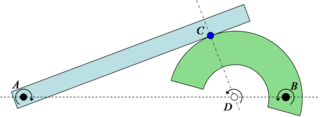
Sketch 4: Instance relative eye of rotation. Two bodies in contact at C, one rotating about A and the other about B must accept a relative center of rotation somewhere along the line AB. Since the parts cannot interpenetrate the relative rotation center must also exist along the normal direction to the contact and through C. The only possible solution is if the relative center is at D.
If 2 planar rigid bodies are in contact, and each body has its own distinct center of rotation, then the relative eye of rotation between the bodies has to lie somewhere on the line connecting the ii centers. As a issue, since pure rolling tin can only exist when the eye of rotation is at the indicate of contact (equally seen above with the bicycle on the road), it is only when the point of contact goes through the line connecting the ii rotation centers that pure rolling can exist achieved. This is known in anfractuous gear pattern every bit the pitch point, where there is no relative sliding between the gears. In fact, the gearing ratio between the 2 rotating parts is found by the ratio of the two distances to the relative center. In the example in Sketch four the gearing ratio is

Instant centre of rotation and mechanisms [edit]
Sketch 1 above shows a four-bar linkage where a number of instant centers of rotation are illustrated. The rigid body noted by the letters BAC is connected with links Pi-A and Ptwo-B to a base or frame.
The iii moving parts of this mechanism (the base of operations is not moving) are: link P1-A, link P2-B, and body BAC. For each of these three parts an instant center of rotation may be determined.
Considering first link P1-A: all points on this link, including point A, rotate around point P1. Since P1 is the just bespeak not moving in the given plane it may be called the instant center of rotation for this link. Bespeak A, at distance P1-A from Pane, moves in a circular motion in a direction perpendicular to the link P1-A, every bit indicated by vector 5A.
The same applies to link P2-B: bespeak P2 is the instant middle of rotation for this link and point B moves in the direction equally indicated by vector 5B.
For determining the instant center of rotation of the tertiary chemical element of the linkage, the trunk BAC, the two points A and B are used because its moving characteristics are known, as derived from the information about the links P1-A and P2-B.
The management of speed of signal A is indicated by vector FiveA. Its instant center of rotation must be perpendicular to this vector (as VA is tangentially located on the circumference of a circle). The only line that fills the requirement is a line colinear with link P1-A. Somewhere on this line there is a point P, the instant middle of rotation for the body BAC.
What applies to point A also applies to signal B, therefore this instant center of rotation P is located on a line perpendicular to vector FiveB, a line colinear with link Pii-B. Therefore, the instant heart of rotation P of body BAC is the point where the lines through Pi-A and P2-B cross.
Since this instant center of rotation P is the eye for all points on the body BAC for any random point, say signal C, the speed and direction of movement may be determined: connect P to C. The direction of movement of point C is perpendicular to this connection. The speed is proportional to the distance to point P.
Continuing this arroyo with the two links Pi-A and Pii-B rotating around their own instant centers of rotation the centrode for instant center of rotation P may be determined. From this the path of motility for C or any other indicate on trunk BAC may be adamant.
Examples of application [edit]
In biomechanical research the instant centre of rotation is observed for the performance of the joints in the upper and lower extremities.[two] For example, in analysing the knee,[iii] [4] [5] ankle,[vi] or shoulder joints.[7] [eight] Such noesis assists in developing artificial joints and prosthesis, such as elbow [nine] or finger joints.[ten]
Report of the joints of horses: "...velocity vectors adamant from the instant centers of rotation indicated that the joint surfaces slide on each other."[eleven]
Studies on turning a vessel moving through h2o.[12]
The braking characteristics of a car may exist improved by varying the design of a restriction pedal mechanism.[thirteen]
Designing the suspension of a wheel,[xiv] or of a motorcar.[15]
In the instance of the coupler link in a four-bar linkage, such every bit a double wishbone interruption in front view, the perpendiculars to the velocity lie forth the links joining the grounded link to the coupler link. This structure is used to establish the kinematic whorl center of the suspension.
Run across besides [edit]
- Athwart velocity
- Burmester's theory
- Centrode
- Rigid body
- Roll center
- Rotation around a fixed centrality
- Spiral axis
References [edit]
- ^ Illustrated Dictionary of Mechanical Engineering: English language, German, French, Dutch, Russian (Springer Science & Business Media, 17 Apr. 2013 - 422 pages)
- ^ "Muscle Physiology — Joint Moment Arm".
- ^ Knee joint movement description and measurement [ permanent dead link ]
- ^ Moorehead JD, Montgomery SC, Harvey DM (Sep 2003). "Instant center of rotation interpretation using the Reuleaux technique and a Lateral Extrapolation technique". J Biomech. 36 (nine): 1301–7. doi:10.1016/S0021-9290(03)00156-8. PMID 12893038.
- ^ Hollman JH, Deusinger RH, Van Dillen LR, Matava MJ (Aug 2003). "Gender differences in surface rolling and gliding kinematics of the knee". Clin Orthop Relat Res. 413 (413): 208–21. doi:10.1097/01.blo.0000072902.36018.fe. PMID 12897612. S2CID 45191914.
- ^ Maganaris CN, Baltzopoulos V, Sargeant AJ (Aug 1998). "Changes in Achilles tendon moment arm from rest to maximum isometric plantarflexion: in vivo observations in man". Journal of Physiology. 510 (Pt 3): 977–85. doi:10.1111/j.1469-7793.1998.977bj.x. PMC2231068. PMID 9660906. Archived from the original on 2012-09-08.
- ^ Biomechanics of shoulder
- ^ Poppen NK, Walker PS (Mar 1976). "Normal and abnormal move of the shoulder". J Os Joint Surg Am. 58 (two): 195–201. doi:ten.2106/00004623-197658020-00006. PMID 1254624.
- ^ US 5030237 Elbow prosthesis
- ^ "Pyrocarbon Finger Joint Implant" (PDF). Archived from the original (PDF) on 2011-07-21. Retrieved 2008-08-22 .
- ^ Colahan P, Piotrowski One thousand, Poulos P (Sep 1988). "Kinematic analysis of the instant centers of rotation of the equine metacarpophalangeal joint". Am J Vet Res. 49 (nine): 1560–5. PMID 3223666.
- ^ "PART Vi Vessel Navigation and Manoeuvering" (PDF). Archived from the original (PDF) on 2009-12-15. Retrieved 2008-08-22 .
- ^ GB 1443270 Variable Mechanical Ratio Brake Pedal Mounts - General Motors, 1976
- ^ United states 7100930 Bicycle rear suspension system
- ^ Reza N. Jazar (2008). Vehicle Dynamics: Theory and Application. Berlin: Springer. ISBN978-0-387-74243-4.

What Is Center Of Rotation,
Source: https://en.wikipedia.org/wiki/Instant_centre_of_rotation
Posted by: gibsonyessund.blogspot.com
0 Response to "What Is Center Of Rotation"
Post a Comment